By Brad Jakubowski
It’s late Friday afternoon in mid-July. You have a 32-team softball tournament that weekend, and the weather forecast is for hot and sunny conditions. Part of your final preparations is to make sure your irrigation system is set to run correctly. You go to the controller and turn on one of the stations, and nothing happens. Of course, it happens late on Friday, and you’re left saying a few choice words with your back against the wall. What do you do next? How do you determine the problem? Can you correct it in time for the tournament? Fortunately, there is a step-by-step process for determining the problem, and it doesn’t have to take an inordinate amount of time. Let’s take a look at that process and go back to basics in troubleshooting your irrigation system’s electronics.
Before we break out all our testing equipment, there are a few simple things to check first. While testing aircraft electronics systems in the Air Force, we would always say, “power in / power out,” to make sure there was correct power to the systems we were checking. So, it would benefit us most to do the same for our irrigation systems. Instead, let’s say, “water in / water out, and then power in / power out.”
There are two first steps in troubleshooting our system:
1. Make sure the water source is turned on and active. (I cannot tell you how many hours I’ve spent – err wasted – not making simple checks like this.)
a. Check the main water source.
b. Test the appropriate isolation valve.
c. Walk out to the field and manually activate the nearest valve.
2. Make sure the power source is turned on and working correctly.
a. Check power going into the controller. (Is the main panel tripped? Is the information screen on the controller blank or blinking? Are any lights on?)
b. Check the fuses in the controller. (These fuses help protect the internal circuitry and the valve solenoids receiving voltage signals.)
c. Activate the next station on the controller. (If all stations are not working, that tells us something as well.)
Once you’ve ensured there is water and power, you can proceed to your next troubleshooting steps. There are three basic measurements used in electrical troubleshooting: volts, amps and ohms. All three measurements can be performed at the controller. To be successful, we must be familiar with these measurements and how they relate to irrigation systems.
Basic principles and terms
Electricity and electronics are both based on the simple principle of electrons flowing through a conductor, which is very similar to water flowing through a pipe. The electrons require pressure and have velocity and experience resistance just as water does flowing through our irrigation systems. Let’s briefly review these similarities.
Voltage (V) is an electrical unit of measure that represents the amount of force or pressure that is exerted on the electrons to “push” them through a conductor or wire. Volts are then very similar to the pounds per square inch (psi) exerted on water in piping.
Ampere (A) is an electrical unit of measure often referred to as “amps” or “current.” Amps represent how fast electrons are traveling through the wire. This current is very similar to the velocity of water flowing through pipes measured in feet per second (fps). Just as irrigation systems can be damaged from water flowing too quickly through pipe, similar damage can result from having too many amps flowing through electrical wiring (overheating and possibly fires). Therefore, we should always use heavier-duty (14ga to 10ga) cords when operating power tools and equipment.
Ohm (R or ꭥ) is an electrical unit of measure referring to the amount of resistance in a circuit. This loss of voltage and current is the same as the friction loss experienced in pipe. Thus, the smaller the wire, the more resistance can be exerted on voltage and current, just like when small-diameter pipe is used in an irrigation system. You can also think of this resistance like having only one lane of traffic available during heavy rush hour instead of three or four lanes.
To successfully troubleshoot electrical systems, it is important to understand how a valve circuit operates and its associated order of operation. Having a solid understanding will enable you to troubleshoot and correct installation problems, improper repairs, or just plain system aging breakdowns.
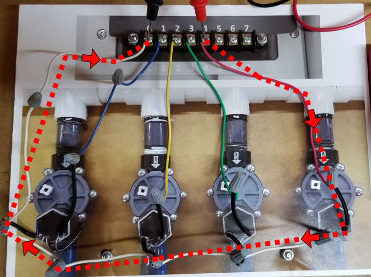
Let’s start with a simple valve system. A circuit consists of one “hot” or station wire (the blue, yellow, green, or red wires from Figure 1) and one common wire (the series of white wires along the bottom and left of Figure 1).

The order of operation for a simple valve system follows:
Step 1: The controller sends a 24-volt signal through the station wire to the solenoid (the red wire on Figure 1).
KEY POINT: We need an initiating signal from the controller, and we need to know how to test if it is operating correctly.
Step 2: The electrical signal travels through the solenoid, generating a magnetic field, causing the solenoid to retract its plunger, initiating valve activation.
KEY POINT: We need to know if the solenoid successfully received and utilized the signal from the controller and how to test it if it did.
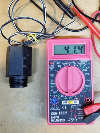
Because the signal is traveling through the solenoid (made up of an incredible number of tiny wire windings), a predictable resistance can be measured, and usually ranges between 20 – 60 ohms. This helps us evaluate the “health” of the solenoid (see Figure 2).
Step 3: The electrical signal travels through the common wire (white wires) back to the controller.
KEY POINT: This returning signal allows us to determine if the system is operating correctly or help us determine where the problem may be located physically.
Now that we understand how the circuit operates, we can start testing each of the steps to determine what our problem may be. Let’s start at the controller.
Testing for step 1 – 24V AC from the controller to the solenoid
First, we need to determine if the controller is sending a proper 24V AC signal to the solenoid. To do this, we would do the following (refer to Figure 1):
Step 1: Turn ON power to the controller.
Step 2: Turn ON the station to be tested.
Step 3: With your multimeter set at the proper AC setting (normally 200 VAC), place its black lead on the common post (indicated by a C) in the controller terminal strip (where all your wires are connected to screws) and the red lead on the station you are testing).
Good result: a display of 23 to 26V AC (optimum range).
Poor result: a display of something near 0V AC or out of the optimum range.
If you get a poor result, check your other stations to determine if the entire controller is at fault or just this one station. If all of them give you this result, it may be a bad transformer or circuit board. Both can be replaced relatively easily if parts are available. You will want to check to see if it is cost effective to replace those parts or the entire controller.
If it is just one single station, it may be a circuit board issue. For the sake of time, move your station wire to another available station if possible or connect it with another station if feasible.
Once you’ve tested the controller, you can move on to testing the circuit beyond the controller and the solenoid.
Testing for step 2 – solenoid is receiving / utilizing the 24V AC signal from the controller
Step 1: Turn OFF the station and or the entire controller. You will be testing for ohms (resistance) and using power from the multimeter to determine if the circuit is complete and if the solenoid is operating correctly.
Note: if the station is still “live” with AC power, you will likely get an inaccurate reading and/or damage your multimeter.
Step 2: Move your multimeter to its lowest range setting (normally 200ꭥ).
Step 3. Place your black lead on the common post and the red lead on the station post being tested.
Good result: An ohm reading of somewhere between 20-60 ohm. This tells you that you have a complete electrical circuit, and that the solenoid is receiving the 24V AC signal properly and is doing what it’s supposed to electronically. (This does not rule out something mechanically problematic with the solenoid. For example, dirt or debris may be restricting movement of the solenoid plunger.)
Bad result 1 – open: A display of 1. ohms or 1000 ohms or higher. This indicates an open circuit, a break in the wire, or a poor waterproof connection in the valve box. It may also mean that the solenoid is bad (possible lightning strike or power surge or just old age).
Bad result 2 – short: A display of 0 to 9 ohms. This is most likely a short circuit. It means you have a complete circuit, but the electrical current is taking a shorter path and not its intended path. This may be caused by the station wire and common wire touching, melted insulation within the solenoid windings, or poor waterproof connections.
Bad Result 3 – partial: A display between 70 and 200 ohms. In this case your circuit is almost complete and may give you intermittent results, resulting in one of the more difficult problems to identify. This is often the result of a poor waterproof connection or a nicked wire that is corroding in the soil.
Now that you’ve tested the circuit, its connections, and the solenoid, you can now work on physically locating some problems. Is it located near station 1 or is it farther down the line? Is it a faulty station wire or is it the common wire? The tests that follow can help you save time in hunting down the fault.
Testing for step 3 – locating potential problems based on resistance readings
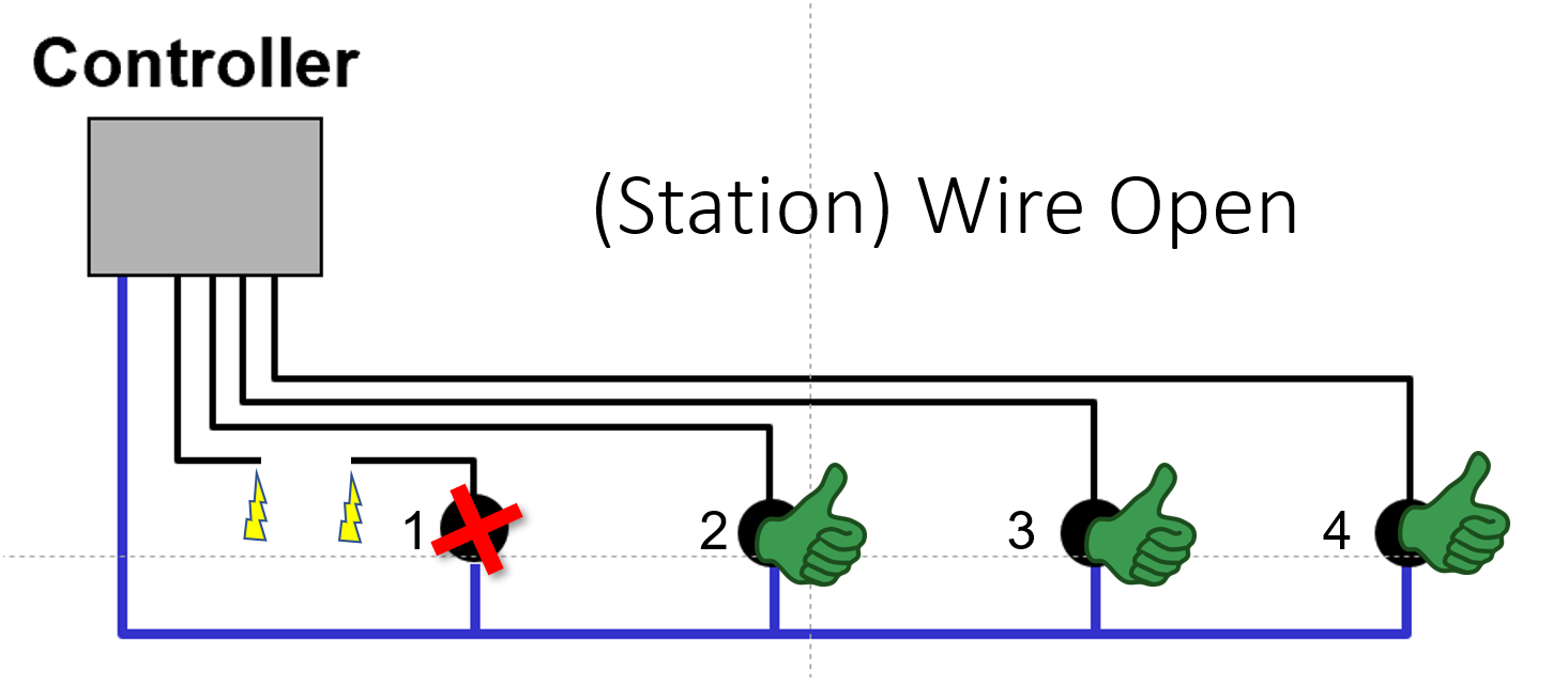
Scenario 1: Station 1 wire open (See Figure 3).
Step 1: Keep AC power OFF.
Step 2. Check resistance of circuit in question. It should display an OPEN reading.
Step 3. Check other stations. They should all display normal resistance readings. This tells you it is just a break with this one station, most likely a bad wire connection in the valve box. If not, ask yourself if you had done any digging or aerifying that may have caused the break.
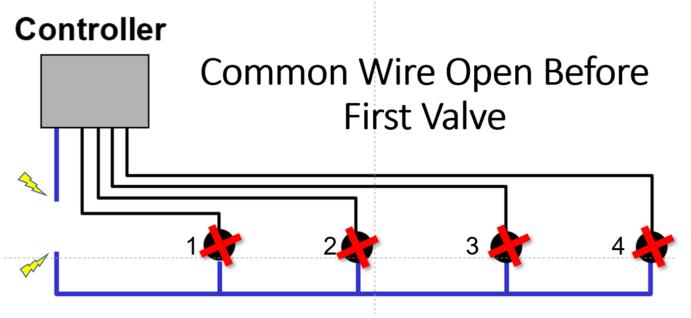
Scenario 2: Common wire open before first valve (See Figure 4).
Step 1: Keep AC power OFF.
Step 2. Check resistance of circuit. It should display an OPEN reading.
Step 3. Check other stations. They should all display OPEN resistance readings. This tells you that the common wire connection is bad somewhere at or before the first valve. The first thing to check would be the common wire splices in the valve box.
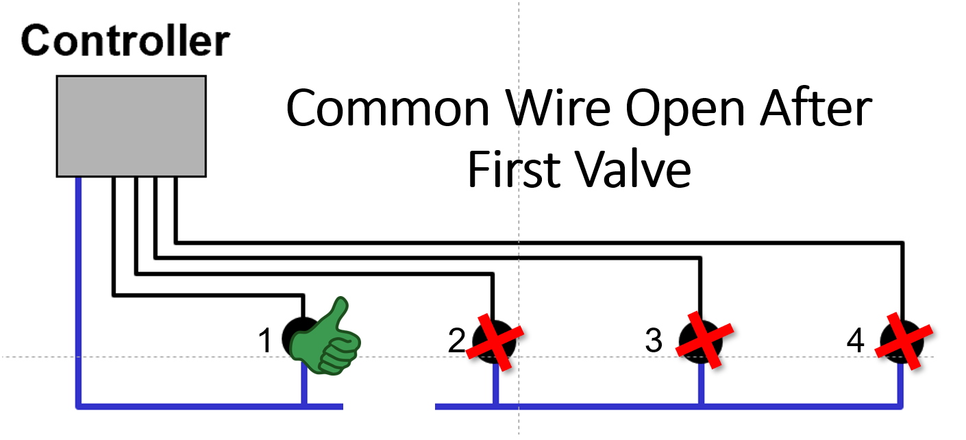
Scenario 3: Common wire open after first valve (See Figure 5).
Step 1: Keep AC power OFF.
Step 2. Check resistance of circuit for station 1. It should display a NORMAL reading.
Step 3. Check other stations. They should all display OPEN resistance readings. This tells you that the common wire connection is bad somewhere after first valve. The first thing to check is the common wire splices in the valve box associated with station 2. The problem will have to be somewhere between those two stations.
These processes and directions should give you a better understanding of how the electrical system of an irrigation system operates and how to troubleshoot your problems more efficiently. So, when it’s late Friday afternoon and the system conks out, you will know exactly what to do and save yourself time and a bit of frustration.
Brad Jakubowski is a turfgrass and irrigation instructor with Penn State University. He is a certified irrigation technician with the Irrigation Association and is an author and presenter covering multiple management areas within the turfgrass industry. He focuses his time on teaching best irrigation practices and troubleshooting, weather-based management decisions, soils and plant nutrition.